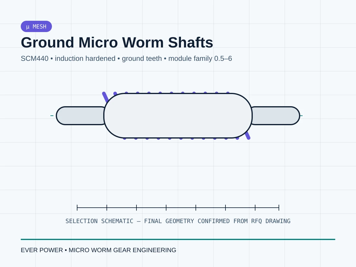
Descrição
Escopo de engenharia
Escolha esta família quando o diâmetro primitivo compacto, um parafuso sem-fim com eixo e uma superfície dentada retificada forem essenciais para o mecanismo. O site concentra-se na extremidade menor da gama de produtos verificados desta família; o preço de uma peça de produção só é cotado após se conhecerem a roda de acoplamento, a distância entre centros, os mancais do eixo e a faixa de operação.
Os valores abaixo descrevem uma família de referência verificada ou, para trabalhos personalizados, as informações que devem ser definidas antes da produção. Eles representam limites de seleção, e não uma garantia de que todas as combinações estejam em estoque. A EVER POWER confirma o desenho final, o par de acoplamento e o processo de fabricação na fase de orçamento.
Parâmetros de referência da família
| Campo de seleção | Base de família de referência / solicitação de cotação |
|---|---|
| Família de módulos de referência | 0,5–6 |
| Número de partidas | 1–2 |
| Família de materiais | SCM440 |
| Tratamento térmico | Endurecimento por indução |
| Acabamento dentário | dentes moídos |
| Família de precisão de referência | 2º ano |
| Família de rodas de acoplamento de módulo pequeno | Roda de bronze de alumínio, módulo 0,5–1,5 |
Importante: Não selecione um parafuso sem-fim e uma coroa de forma independente, baseando-se apenas no módulo. O número de entradas, o sentido da hélice, a relação de transmissão, a distância entre centros, o sistema de dentes e a geometria de montagem devem formar um par compatível.
Onde esta família de produtos é utilizada
As microengrenagens sem-fim são úteis quando um projetista precisa de transmissão de potência em ângulo reto e redução substancial em um formato compacto. Os contextos típicos de projeto para essa família incluem:
- mecanismos de posicionamento compactos
- pequenos atuadores elétricos
- dispositivos de inspeção e teste
- acionamentos de ajuste de instrumentos
Os exemplos de aplicação descrevem contextos comuns de engenharia, não a adequação certificada. Os requisitos de carga, velocidade, regime de trabalho, lubrificante, temperatura e segurança continuam sendo entradas do projeto.
Revisão de personalização e desenho
Para obter uma citação útil, identifique os itens que controlam a interface e a malha. Podemos analisar:
- módulo e número de partidas
- hélice dextrógira ou levógira
- Diâmetros do munhão do eixo e assentos dos mancais
- Detalhes de chaveta, superfície plana, furo transversal ou rosca
- distância entre centros e geometria da roda de acoplamento
- requisitos de tratamento térmico e inspeção
Caso já exista um componente de acoplamento, forneça o desenho ou uma amostra de referência. Para trabalhos de substituição, inclua o sentido de rotação, a distância entre centros de instalação e fotos da malha original, se disponíveis.
Lista de verificação para inspeção e solicitação de cotação
Geometria
- sistema de módulo ou passo
- A minhoca começa e a mão
- número de dentes da roda / relação alvo
- distância central
- dimensões do eixo, furo e cubo
Dados operacionais
- velocidade de entrada e torque de saída esperado
- ciclo de trabalho e frequência de reversão
- método de lubrificação
- temperatura e ambiente
- quantidade necessária e destino
Compensações de seleção
Um par de engrenagens helicoidais de pequeno porte deve ser selecionado como sistema. Aumentar a redução, reduzir o envelope de contato, alterar o número de entradas, diminuir a folga ou trocar o material da engrenagem podem alterar as condições de contato, as reações dos mancais, a geração de calor e a capacidade de fabricação simultaneamente. Portanto, uma solicitação de cotação (RFP) prática inclui a função desejada e as restrições mecânicas fixas, em vez de especificar um campo do catálogo isoladamente.
Quando o espaço for muito limitado, priorize as dimensões que definem a posição da engrenagem: eixos dos eixos, alojamentos dos rolamentos, referência do furo da roda/cubo e distância entre centros. Perfis externos não funcionais geralmente podem ser discutidos posteriormente. Quando a precisão for crucial, defina o erro visível na saída do mecanismo para que as tolerâncias dos dentes e da montagem possam ser alocadas de forma inteligente.
Planejamento de fabricação e qualidade
O planejamento da produção depende da disponibilidade de material, do torneamento ou preparação do furo, da geração dos dentes, de qualquer operação de tratamento térmico, do acabamento final e da inspeção. Uma família de rodas com rosca sem-fim retificada segue um processo diferente de uma família com rosca sem-fim cortada, enquanto rodas de bronze e polímero utilizam materiais e controles de usinagem diferentes. O orçamento identificará o processo proposto após a análise do desenho e da quantidade.
Para amostras, registre qualquer ajuste de montagem feito durante o teste. Se calços, pré-carga do rolamento, lubrificação ou posição da peça de acoplamento foram alterados para que a amostra funcionasse, atualize a condição de montagem liberada antes da repetição da produção. Para pedidos recorrentes, identifique as características que precisam de registros de lote para que o esforço de inspeção permaneça consistente e útil.
Perguntas frequentes de engenharia
Posso encomendar apenas a rosca sem-fim ou apenas a roda?
Sim, mas ainda é necessário identificar a peça de acoplamento existente. Compartilhe o desenho, o sistema de módulo/passo, o número de entradas ou dentes, a distância entre centros e a posição de instalação para que a compatibilidade possa ser verificada.
Você pode fazer um orçamento com base em uma amostra usada?
Uma amostra ajuda, mas o desgaste pode distorcer a espessura dos dentes e as dimensões externas. As dimensões da carcaça, uma peça de acoplamento sem desgaste ou o desenho original aumentam a confiabilidade da engenharia reversa.
Um par de microvermes pode ser tratado como autotravante?
Nenhuma informação genérica de catálogo deve ser usada como premissa de segurança. O movimento reverso depende da geometria, atrito, lubrificação, carga, vibração e desgaste. Utilize um método de retenção validado quando for necessário impedir o movimento reverso.